Modify STL 3D printing files with FreeCAD – Pinter Computing |
您所在的位置:网站首页 › freecad stl › Modify STL 3D printing files with FreeCAD – Pinter Computing |
Modify STL 3D printing files with FreeCAD – Pinter Computing
|
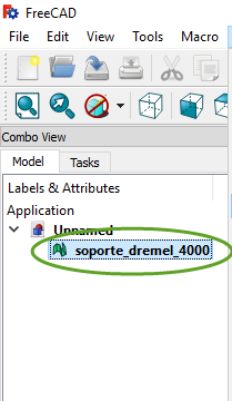
There are many free STL files are available on the internet to 3D print useful objects at home. There are times when we want to make some adjustments to them to better fit our need or 3D printing equipment. If the STL file describes an object that is larger than the maximum dimensions your printer can produce, you can print the object in two or more pieces and glue them together. There are glues on the market that can make as strong bonds as the materials themselves they are attaching together. There are free applications that can open and edit STL files, one of them is the open source FreeCAD. Download FreeCAD from https://www.freecadweb.org/wiki/Download Open and edit STL files in FreeCAD Import an STL file into FreeCAD Start FreeCAD and create a new document with File > New, In the menu select File > Import and navigate to the mesh file you want to modify. FreeCAD can open STL, OBJ, and AST mesh files. In the dropdown select the Part workbench,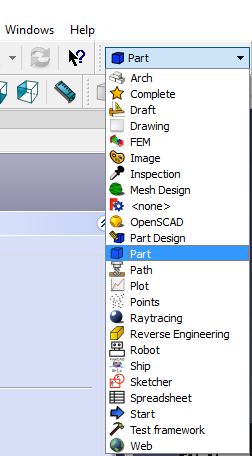 In the Model window select the imported mesh,
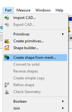
 In the menu select Part > Create shape from mesh…
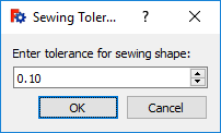
 The default 0.10 tolerance is usually fine for most of the objects we 3D print, click OK,
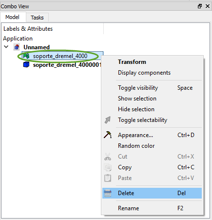
 Delete the imported mesh in the Model window. Right-click the name of the imported mesh and select Delete,
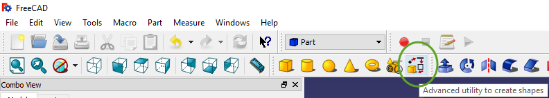
 Convert the shapes to solid. In the toolbar click the Advanced Utilities icon,
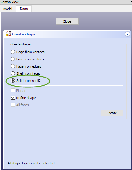
 In the Tasks window select Solid from shell
 Click one triangle on the object,
Click the Create button. You will not notice any change because the solid overlaps the shape.
Click the Close button in the Tasks window,
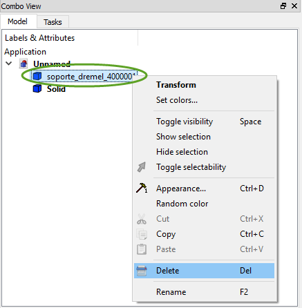
Delete the shape. In the Model window right-click the name of the shape and select Delete. We have converted the mesh to solid, ready to be edited.
Click one triangle on the object,
Click the Create button. You will not notice any change because the solid overlaps the shape.
Click the Close button in the Tasks window,
Delete the shape. In the Model window right-click the name of the shape and select Delete. We have converted the mesh to solid, ready to be edited.
 Edit the solid model in FreeCAD
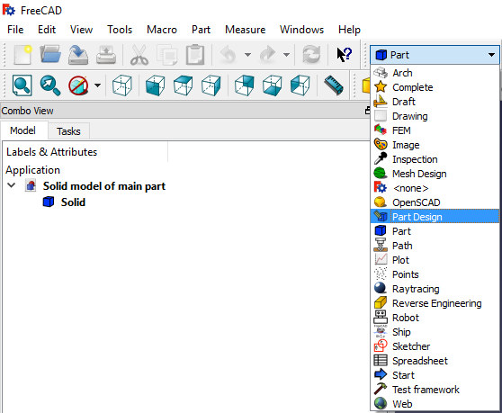
To add or remove parts, open the Part Design workbench,
Edit the solid model in FreeCAD
To add or remove parts, open the Part Design workbench,
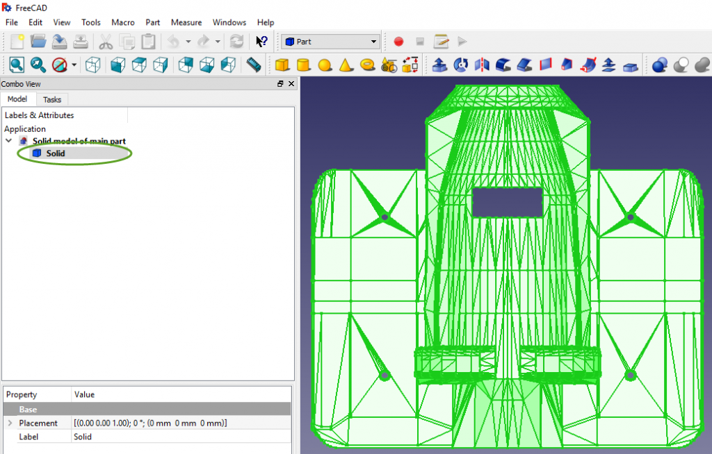
 Select the Solid in the Model window, so the object turns green,
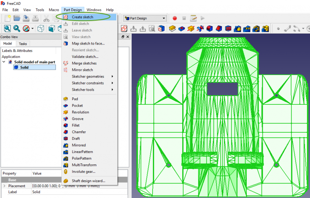
 In the Part Design menu select Create Sketch
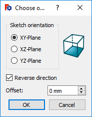
 Select the plane you want to draw and click OK,
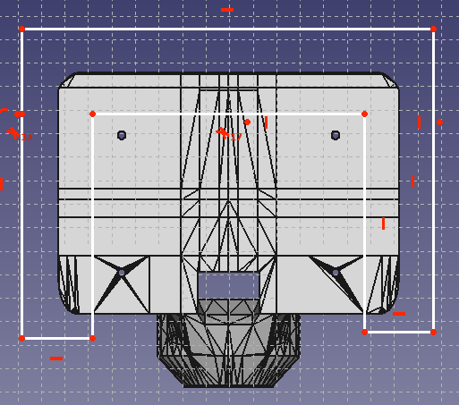
 Draw lines, circles, rectangles that we will extrude to add or subtract them from the object. Don’t worry if the sketch is not at the correct elevation, we will move the sketch to the correct elevation later.
To print a portion of a too large object, draw lines and trim them at the location where you want to separate the object into multiple parts.
Draw lines, circles, rectangles that we will extrude to add or subtract them from the object. Don’t worry if the sketch is not at the correct elevation, we will move the sketch to the correct elevation later.
To print a portion of a too large object, draw lines and trim them at the location where you want to separate the object into multiple parts.
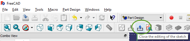
 To close and save the sketch click the Close Sketch icon in the tool bar.
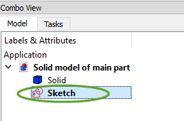
 To continue to edit the sketch, double click it in the Model window.
 To change the elevation of a sketch
Select a face on the solid the move the sketch to,
To change the elevation of a sketch
Select a face on the solid the move the sketch to,
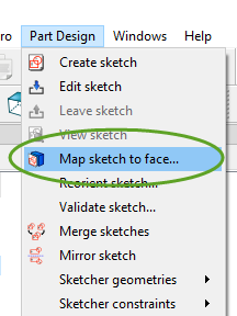
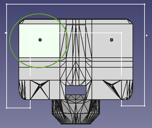 In the Part Design menu select Map sketch to face…
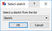
 Select the sketch in the drop-down list and click OK,
 The sketch opens. You can continue the editing of it, or just close it.
|
【本文地址】